
Welding Rotator Buying Guide: Capacity, Speed, and Control
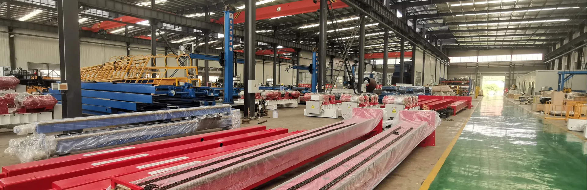
Welding rotators look simple from a distance: two sets of wheels, a frame, a drive. Yet the specification sheet behind them decides whether a fabrication shop produces consistent circumferential welds or spends its days chasing arc wander and rework. Buyers who treat capacity, rotation speed, and control as three independent checkboxes often end up with a machine that either stalls under a heavy vessel or turns too fast for a delicate root pass. The three variables are interdependent — load determines wheel loading, wheel loading constrains available torque, and torque sets the usable speed range under control. This guide walks through each specification in the order a buyer should evaluate it, with the practical checks that separate a rotator that runs for fifteen years from one that disappoints in six months.
Capacity is quoted as a single tonnage figure, which makes it the easiest spec to compare and the easiest to misread. That figure normally assumes the workpiece center of gravity sits close to the rotational axis, with the load shared evenly between the two wheel sets. Real vessels rarely cooperate.
A shell with a heavy nozzle cluster, an offset manway, or internal baffles shifts the center of gravity away from the axis, and the load on one wheel set rises while the other drops. For eccentric or asymmetric workpieces, effective wheel loading can exceed the nominal figure by 15 to 25 percent. Rather than applying a blanket derating factor, send the supplier your actual part drawing and ask for a wheel-load calculation. A reputable manufacturer will run that number before quoting, not after the machine is on your floor.
Also confirm whether the rating applies to the rotating load alone or includes tooling, fixturing, and a welding head mounted on the frame. Accessories add weight that the drive still has to turn.
Wheels are where capacity becomes physical. Three decisions matter:
BOTA sizes wheel sets and wheelbases against part drawings rather than catalog ranges, because a rotator that technically fits a diameter but contacts the shell at the wrong angle will slip under load.
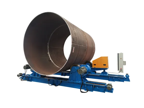
Most circumferential welding falls somewhere between roughly 0.1 and 1.0 rpm, but the top speed on a datasheet tells you very little. The number that matters is the lowest stable speed the unit can hold under full load without stalling, surging, or cogging.
A fixed-speed rotator suits one repetitive job and nothing else. As soon as your workpiece diameter, wall thickness, or process changes, travel speed has to change with it. Three drive approaches dominate the market:
Ask for a torque curve, not just a horsepower rating. A drive that turns 5 rpm freely may stall at 0.2 rpm with a 20-ton vessel on the wheels. Look at the turn-down ratio — the span between maximum and minimum controllable speed — and confirm that the low end is rated at full load. If the answer is vague, the low-speed performance probably is too.
Control is the specification buyers most often under-budget, and the one that most affects daily productivity. A welder who has to walk to a fixed panel to nudge rotation speed loses arc time on every pass.
Hardwired pendants are the baseline and remain the most reliable choice in dirty or high-interference environments. Radio remotes give the operator freedom to stand at the arc, which matters on large-diameter vessels where the weld seam is far from the base. Foot controls are useful for tacking and fit-up work where both hands are occupied with the torch.
Long vessels supported by two rotator units need the drive and idler to hold the same surface speed. Without synchronization, the workpiece creeps axially — slowly at first, then continuously, until the welding head drifts off the seam. Electronic synchronization with a master-slave drive arrangement, plus forward and reverse jog, is standard practice on multi-unit installations.
For automated or high-volume work, look for controls that accept an external speed reference. This lets the welding power source, column and boom, or seam tracker command rotation speed directly, keeping travel speed constant as the torch moves. BOTA configures control packages around the welding process rather than around a stock panel, which is why the interface question belongs in the original inquiry.
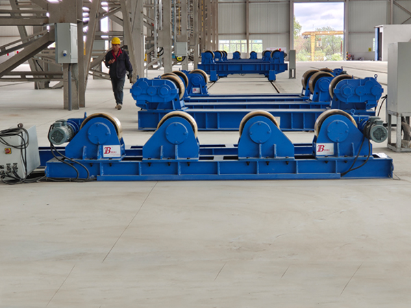
Once capacity, speed, and control are clear, the remaining decision is mechanical configuration. Each type favors a different production profile.

Can one rotator handle both small pipes and large tanks?
Only within its wheelbase and speed range. A unit sized for a 6-meter tank will not hold the low rotation speed needed for a small-diameter pipe, and a small unit cannot carry the tank load. Two correctly sized machines usually cost less than one oversized compromise.
Why does my workpiece drift sideways during welding?
Axial creep almost always points to a speed mismatch between drive and idler units, or to wheel alignment that is not parallel to the vessel axis. Check synchronization settings and wheel parallelism before assuming the load is too heavy.
Is a higher-capacity rotator always the safer purchase?
No. Oversizing raises the minimum controllable speed and can make low-speed welding harder to hold. Specify for your real load range, with a reasonable margin, rather than buying the largest unit your budget allows.
Capacity, speed, and control are not three separate purchases — they are one specification expressed three ways. Get the wheel-load calculation right, confirm low-speed torque at full load, and choose a control interface that keeps the operator at the arc. Buyers who work through those three points in order, with a supplier willing to calculate rather than quote from a catalog, end up with a rotator that holds travel speed pass after pass and still runs smoothly a decade later.
No. 1 Intersection of Chuangye Avenue and Weilai Avenue,
Yiyang County,Luoyang City, Henan Province, China
+86 400-0379-069
Copyright © 2023 An Automated Welding and Cutting Equipment Manufacturer Focusing on Welding Column Boom and Welding Rotator | All Rights Reserved Technical support: ShangXian